The best of technology in the smallest member of the family
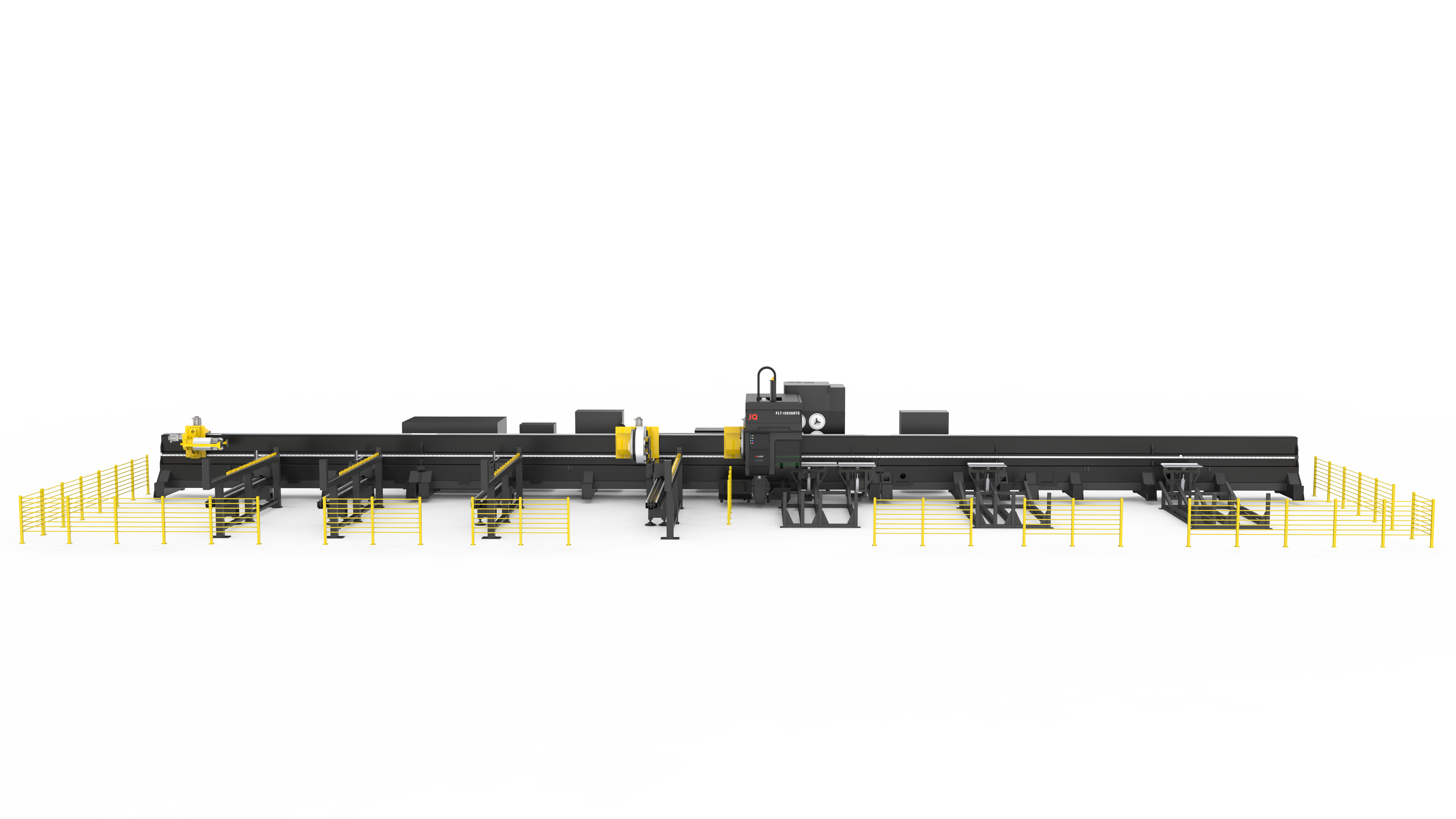
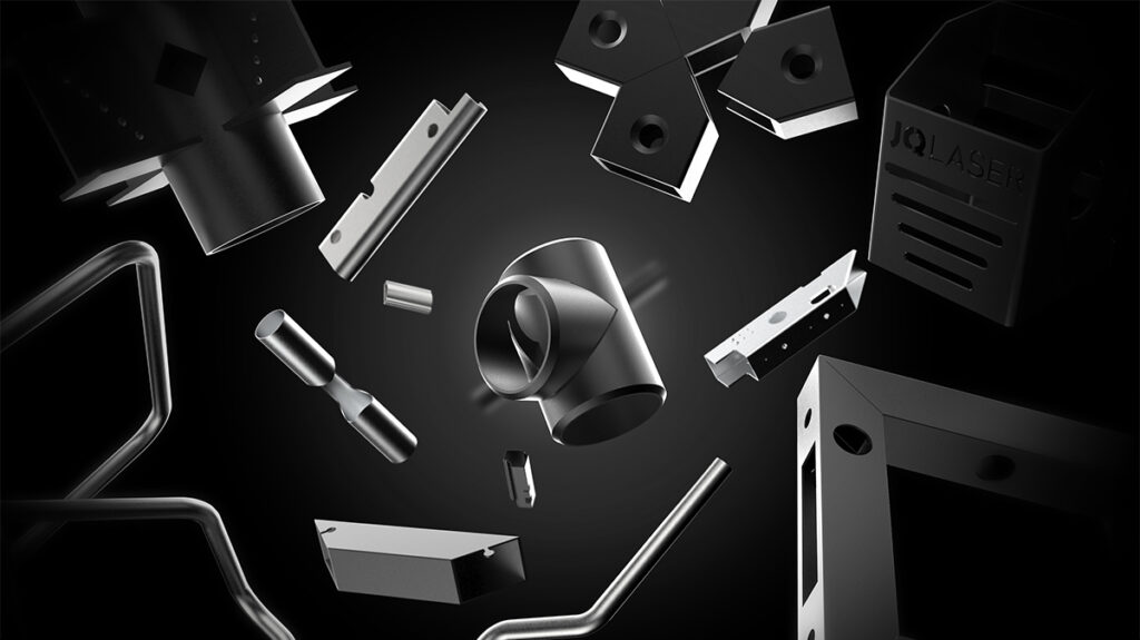
HT360 (square card) chain series is a star series product independently developed by our company with invention patents and software copyrights. The 360 series products are widely used in CNC laser cutting machines for cutting round tubes, square tubes, rectangular tubes, H-shaped steel, angle steel, and channel steel made of ordinary carbon steel, stainless steel, etc.
Performance based on robustness and, above all, reliability.
Ergonomic and accessible
The main components of the HT360 series laser tube cutting machine are: machine bed, gantry system, intelligent loading system, intelligent unloading system, chuck, electrical control system, laser, chiller, cutting head, lubrication system, pneumatic system, dust removal system (optional), safety system (optional), etc.
Form and content in a single solution
The best choices show their value over time
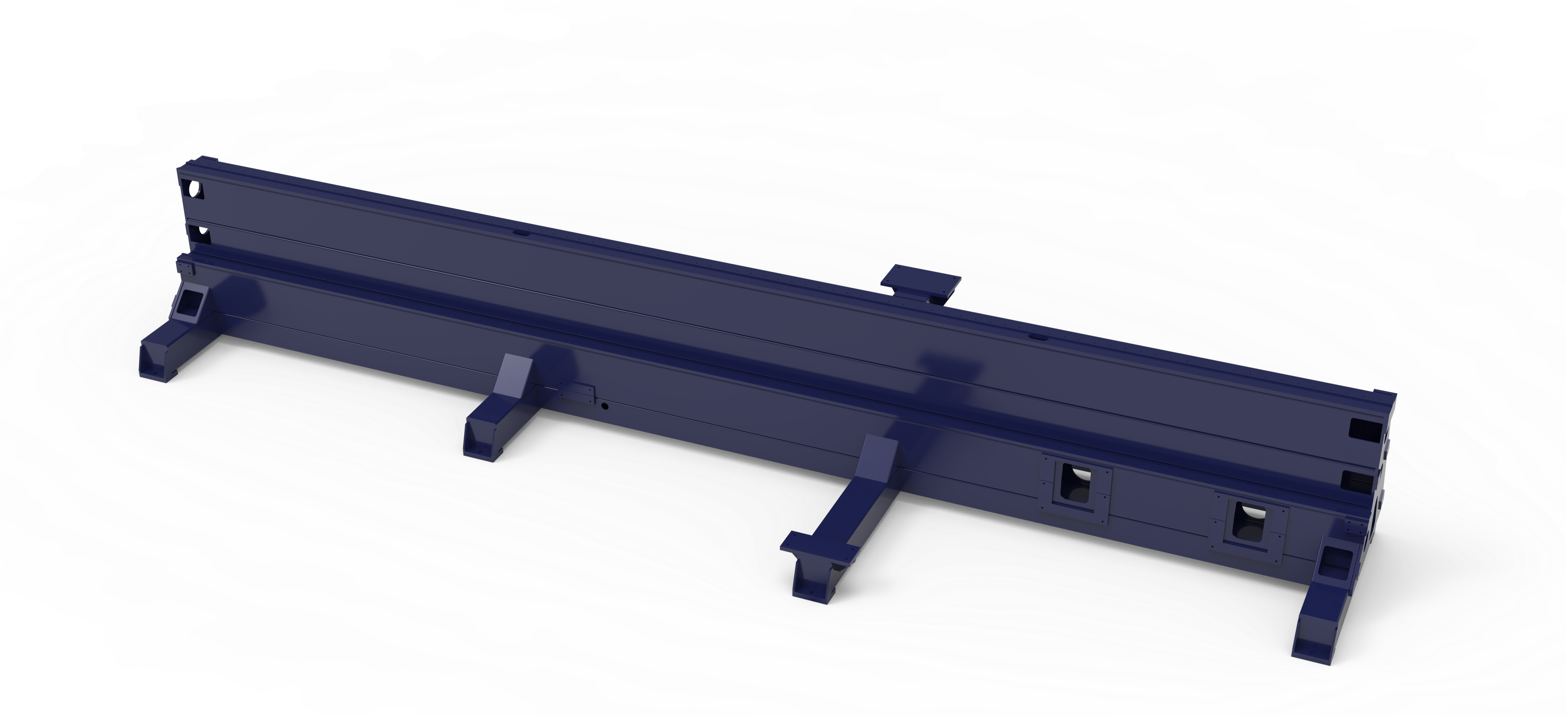
Machine tool beds
The bed and the chuck are connected by a side-mounted design, so the operator can load and unload large materials more conveniently. The bed is welded by square tubes and unequal steel plates, connected by high-strength bolts and fixed plates to ensure the geometric accuracy after connection. After welding, annealing is performed to eliminate internal stress, and vibration aging is performed after rough machining and then fine machining is performed, which greatly improves the rigidity and stability of the machine tool and ensures the accuracy of the machine tool.
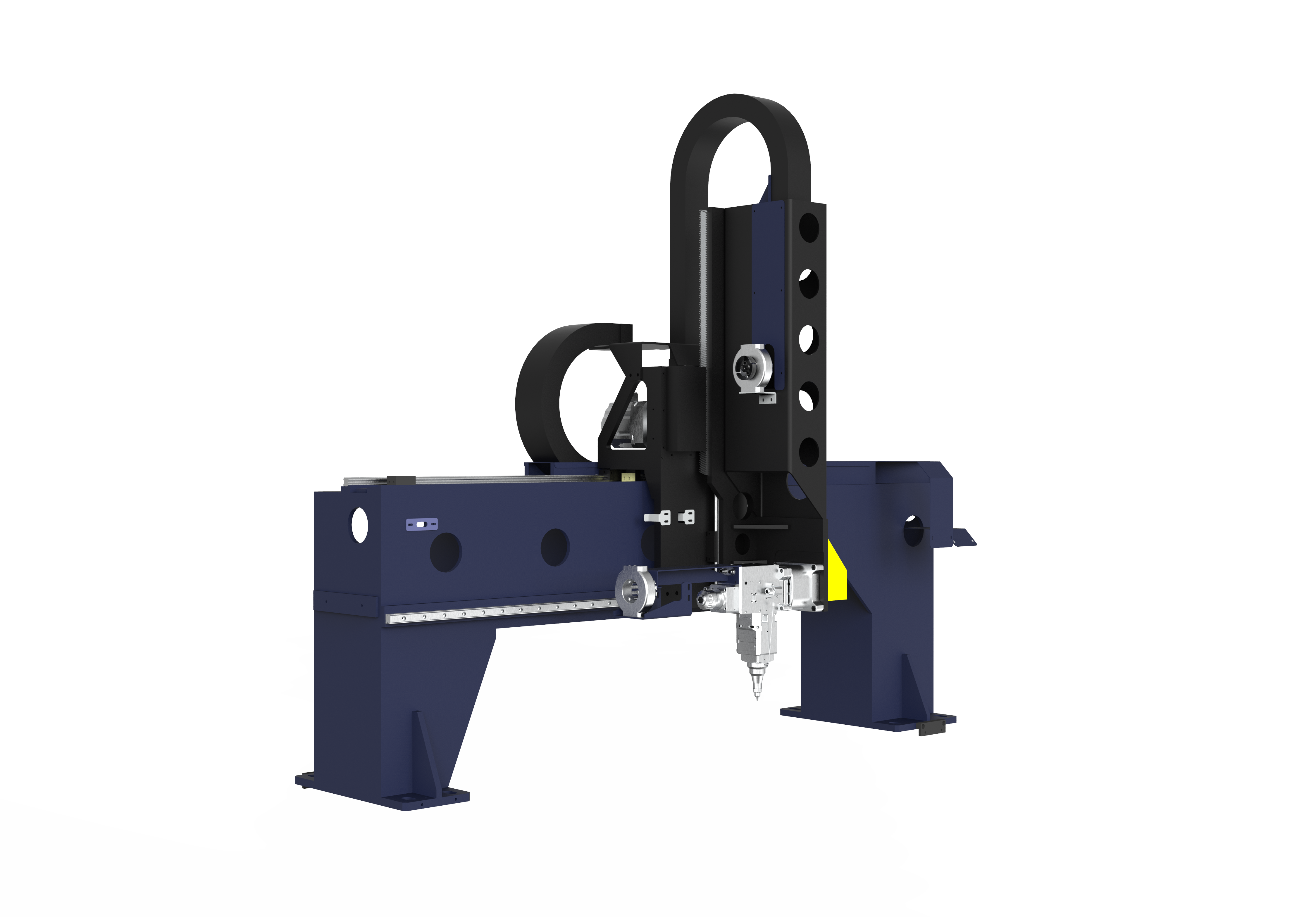
Gantry system
The X-axis crossbeam and side columns adopt a gantry structure, which is made of high-quality carbon steel plates welded as a whole. After annealing to eliminate internal stress, rough machining, aging treatment and fine machining are performed to ensure the rigidity and stability of the laser head moving components. The crossbeam is fixed on the bed, equipped with high-quality linear guides, driven by servo motors, and driven by high-quality gear racks, so that the Z-axis slide can achieve reciprocating motion in the X direction. During the movement, the limit switch controls the stroke to limit the position, and there are mechanical limits at both ends to ensure the safety of system operation.
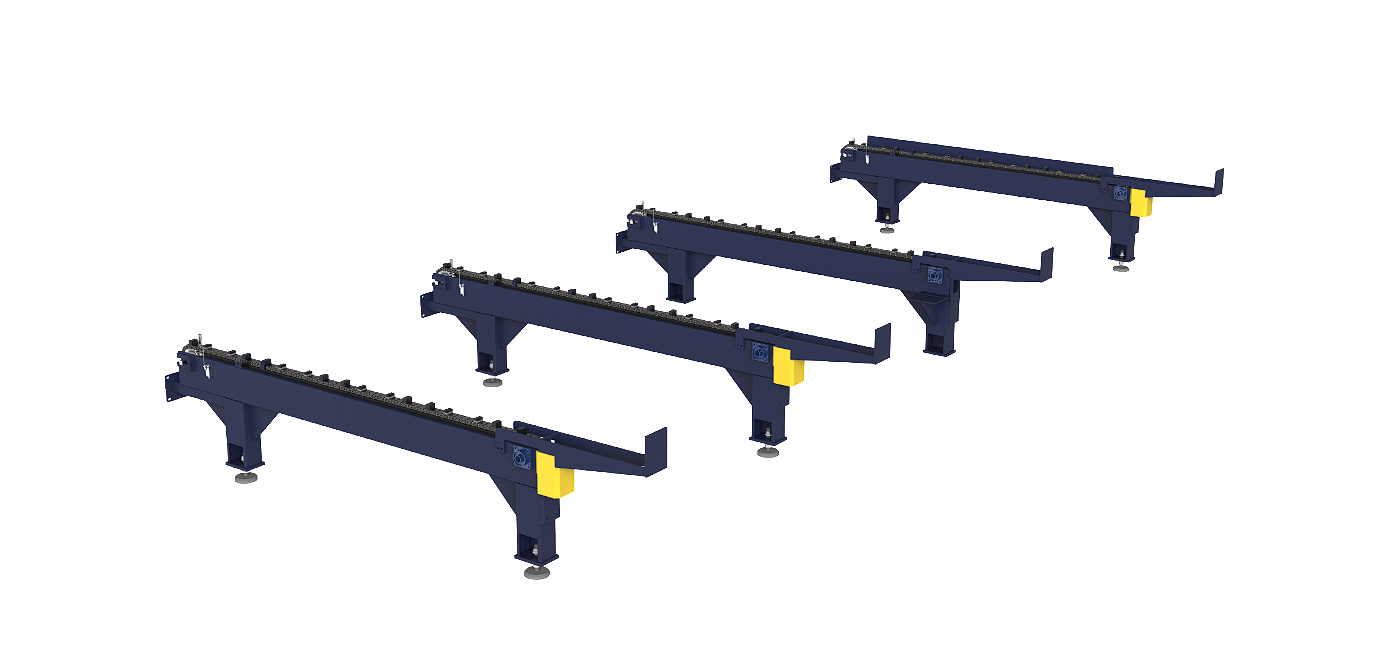
Intelligent feeding system
The feeding side is designed with an intelligent chain feeding system. The system adopts the front-alignment method to place the raw materials in the vacant positions of the feeding rack chain in sequence. The feeding system uses servo control to transport the materials on the chain to the main machine feeding area, and then controls the lifting of the supporting device through the servo system. The raw materials are lifted to a suitable height through servo positioning control, and the raw materials are automatically centered and then transported to the chuck clamping position through servo positioning control. During the motion control process, the servo control uses encoder positioning, and there are mechanical limits at both ends to ensure the safety of system operation.
Intelligent unloading system
Category
Introduction
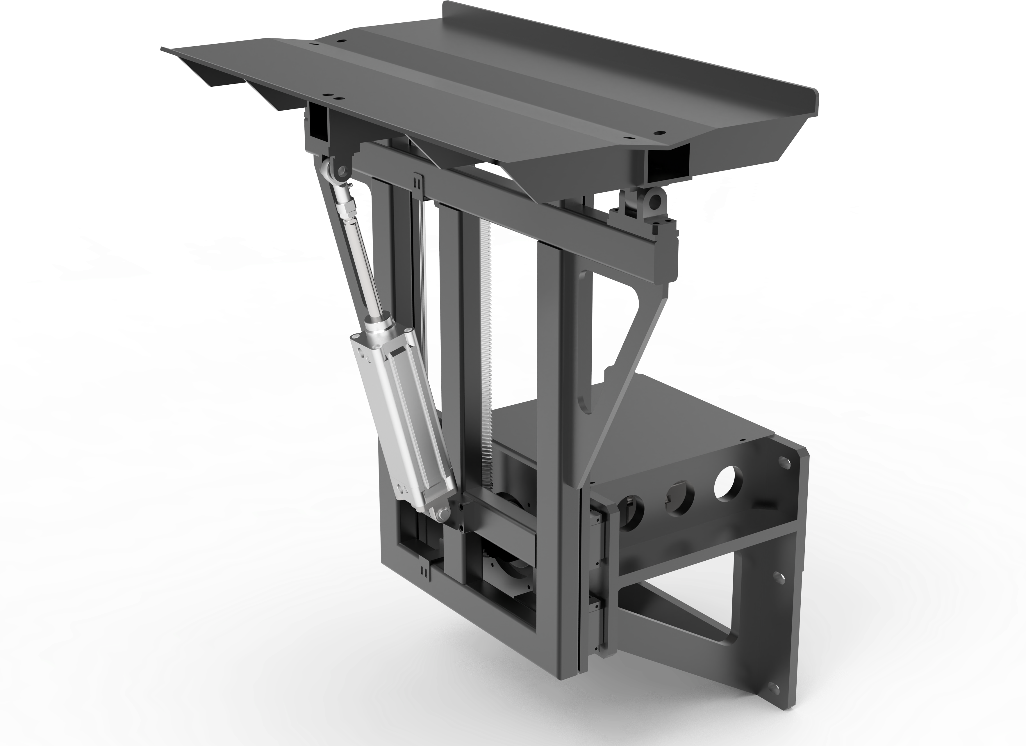
Flip unloading
It has a flipping function, which is realized by the solenoid valve controlling the cylinder; the workpiece after cutting can be flipped onto the storage rack, and the workpiece slides out sideways along the storage rack.
Chain unloading
After the workpiece is cut, it can be dropped onto the unloading rack chain and then transported to an empty station for temporary storage. The entire conveying process is smooth and orderly with less impact.
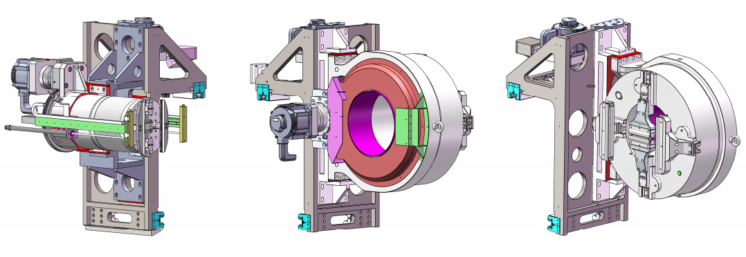
Chunk
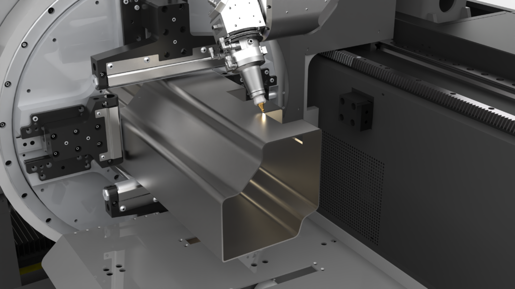
The three sets of chucks are driven by servo motors and can move and rotate synchronously in the Y-axis direction. Under the logical action set by the system, the pipe can be pulled and cut, which greatly improves the cutting accuracy and can conditionally achieve zero tail material cutting (depending on the workpiece cutting size and specific cutting process).
The chuck Y-axis motion drive rack, linear guide rail, and W-axis rotation drive gear are all high-precision products, which effectively ensure the transmission accuracy; each set of chucks is equipped with limit switch control and hard limit device, which effectively ensures the safety of machine tool movement.
The rear chuck is designed with a detection sensor to detect the tail end position of the pipe, so as to realize the automatic clamping of the pipe by the rear chuck and complete the automatic feeding process. A detection sensor is also designed on the rear side of the middle chuck. When the rear chuck pushes the pipe to feed, the sensor detects the front end position of the pipe.
The sensor transmits the signal to the CNC system, and the system controls the rear chuck to accurately send the pipe to the pre-cutting position. According to the customer’s process requirements, the pipe can be processed with or without ends.
Electrical control system
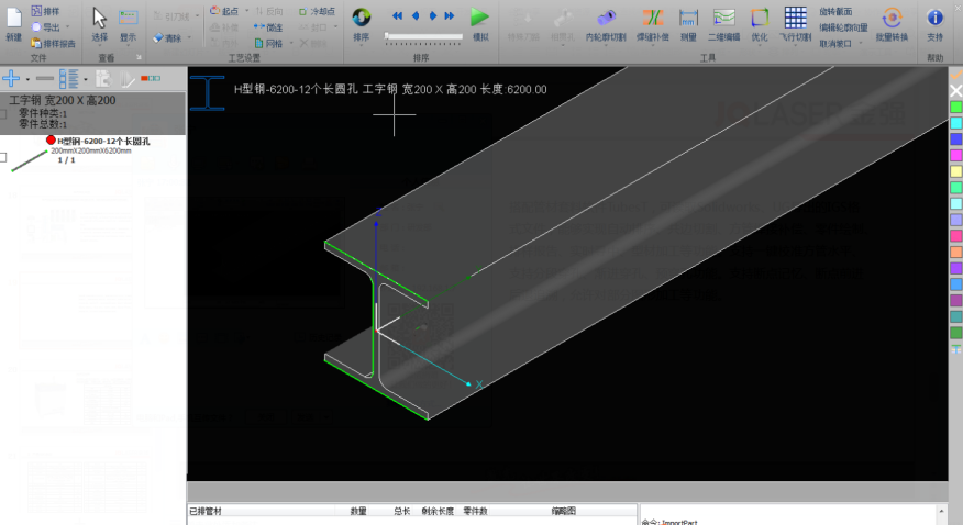
Optional pipe nesting software can read IGS format files exported by Solidworks, UG, and Pro/E, and can realize functions such as automatic sorting, common edge cutting, square pipe welding compensation, part drawing, nesting report, real-time centering, and profile processing. It supports one-key calibration of square pipe level, segmented perforation, and progressive perforation. It supports breakpoint memory, breakpoint forward and backward tracing, and allows partial graphics processing.
The software suite that creates value
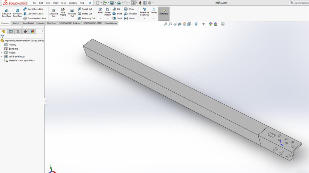
Design of parts and frames in a three-dimensional graphical CAD/CAM environment designed to exploit every performance margin of the Lasertubes. Libraries of functions that speed up and simplify design on the tube. Accurate batch time and cost estimates for a detailed estimate. Remote planning and real-time monitoring of work in progress.
All this and more makes a difference every day in terms of being able to make full use of a laser cutting system, reducing unproductive downtime times and eliminating waste. A choice of value also involves software.
Are you wondering whether these features are ideal for your goals?